Strobe the decoder with your own hands

Communication for those wishing to do something with their hands.
User avatar
Гуру
Posts:5
Joined:Sun Mar 30, 2008 23:48

Post by Гуру » Wed Apr 02, 2008 1:50

Somewhere I have rolled a full description of the LM567.
if necessary lay out.
who doesn't Have oscila tank here http://xgurux.ucoz.ru/tester.rar
there are interesting prog but no cracks
as will picks open lay out with a Paci.
R. S. guest I :)

АлексанрД

Post by АлексанрД » Wed Apr 02, 2008 5:09

Гость wrote:what's the problem?
put capacitor
Better resistor divider or just limiting resistor, the capacitor has resistance and there is no possibility to see a constant component

Сергей Владимирович
Posts:30
Joined:Tue Mar 20, 2007 5:39

Post by Сергей Владимирович » Thu Apr 03, 2008 7:23

Hello!
I was thinking about it. In any modern computer has a sound card with multiple channels of audio output. If You have a burning desire to collect AudioStrobe decoder, why not output sound and AudioStrobe signal through separate outputs of the sound card. Enough to dig online and find many sound editors and multi-channel mixers, allowing to create the necessary number of audio tracks. Now, taking any AudioStrobe disk, you can save it as two files, one original and the other with the cut-off frequencies up to 19200 Hz. Then send the audio from these files on two independent channels. To the channel, reproducing the AudioStrobe signal, you can connect a simple device (even simpler than the decoder LM567), consisting of a RF detector diode, a transistor operating in key mode, and several parts (like a simple light setup). By the way, somewhere around the circuit on optocouplers enable you to control the brightness of the LEDs depending on the output level. Who should - share.
Good luck!

User avatar
Лайтмен
Posts:17
Joined:Sat Mar 08, 2008 13:38

Post by Лайтмен » Fri Apr 04, 2008 1:12

2 Guru: datasheet for LM 567 is elementary by Google ;)
2 Sergey Vladimirovich: For playing multichannel audio (more than stereo) and the corresponding desired soft - Winamp is unlikely to pull, especially if split into two files. And run they will have simultaneously. And process each one before playing, i.e. without the possibility of reproducing "real-time", as the same BWGen. And one more restriction: only the computer (in the usual case, the sound can be fed even with the MP3 player)... IMHO, it's not worth it - why so many just turn up, when a simple diagram on the LM567 is quite easy to cope with its task ? ;) And interference will understand =) Sorry, now with time is tight...

User avatar
Гуру
Posts:5
Joined:Sun Mar 30, 2008 23:48

Post by Гуру » Fri Apr 04, 2008 1:14

I was thinking about it. In any modern computer has a sound card with multiple channels of audio output. If You have a burning desire to collect AudioStrobe decoder, why not output sound and AudioStrobe signal through separate outputs of the sound card. Enough to dig online and find many sound editors and multi-channel mixers, allowing to create the necessary number of audio tracks. Now, taking any AudioStrobe disk, you can save it as two files, one original and the other with the cut-off frequencies up to 19200 Hz. Then send the audio from these files on two independent channels. To the channel, reproducing the AudioStrobe signal, you can connect a simple device (even simpler than the decoder LM567), consisting of a RF detector diode, a transistor operating in key mode, and several parts (like a simple light setup). By the way, somewhere around the circuit on optocouplers enable you to control the brightness of the LEDs depending on the output level. Who should - share.
Good luck!
Why to complicate your life? before the LM567 decoders to drive the RF filter on OU.
the program for the calculations of the filters can be contracted here

http://focus.ti.com/lit/sw/slvc003d/slvc003d.zip
the program itself according to the specified parameters considers values, draws graphics and layout.
in General, useful not only for gate decoder :)

User avatar
Гуру
Posts:5
Joined:Sun Mar 30, 2008 23:48

Post by Гуру » Fri Apr 04, 2008 1:20

Lightman: ...simple diagram on the LM567 quite easily copes with its task
Toto and ANO, Yes only this "stuff" to other frequencies respond.

Тасев Александр

Post by Тасев Александр » Sun May 04, 2008 11:50

The output of the filter at 567 th, there is no digital signal and a sine wave. The LEDs will now blink soft. IMHO

Андрей Патрушев
Автор сайта
Posts:10238
Joined:Tue May 30, 2006 20:17
Has thanked: 134 times
Been thanked: 556 times

Post by Андрей Патрушев » Mon May 05, 2008 9:47

Тасев Александр wrote:the filter Output at 567 th, there is no digital signal and a sine wave. The LEDs will now blink soft. IMHO
And boring, IMHO. :)

Тасев Александр

Post by Тасев Александр » Tue May 06, 2008 11:17

:shock: I thought that there must be two flashes: "soft" sinusoidal "hard" rectangular. Like all mindmachine...

Андрей Патрушев
Автор сайта
Posts:10238
Joined:Tue May 30, 2006 20:17
Has thanked: 134 times
Been thanked: 556 times

Post by Андрей Патрушев » Wed May 07, 2008 12:37

Тасев Александр wrote::shock: I thought that there must be two flashes: "soft" sinusoidal "hard" rectangular. Like all mindmachine...
In normal strb-decoder signal points served depending on the disc signal.

Тасев Александр

Post by Тасев Александр » Fri May 09, 2008 9:00

Андрей Патрушев wrote:
Тасев Александр wrote::shock: I thought that there must be two flashes: "soft" sinusoidal "hard" rectangular. Like all mindmachine...
In normal strb-decoder signal points served depending on the disc signal.
You want to say can be written and sine and square wave, and triangular wave visual stimulati? At LMa in the scheme of MDM is said all the time, use a digital output. Is always a square wave.

Тасев Александр

Post by Тасев Александр » Fri May 16, 2008 21:43

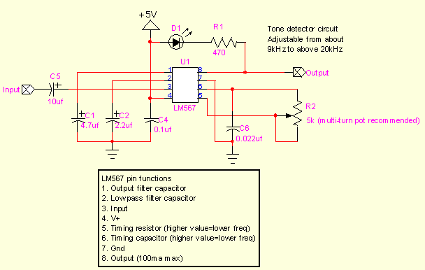
:D The diagram LM567 works. At the correct installation and serviceable details. :)
Keep in mind that an important volume on the output of the sound card.
Because of the narrowness of the features of the filter, the smaller the smaller the amplitude of the input signal. So in the data sheet.
The filter on the frequency of 19200 Hz was configured, to generate a wave (sine wave) in the sound editor Audacity.
Then I picked up the amplitude of the input signal, so that when you turn off Audiostrob'e BWGen when playing presets no flares.
All without an oscilloscope 8) because I support budget decisions :?

Тасев Александр

Post by Тасев Александр » Fri May 16, 2008 21:51

PS. ie ... if it is wrong to set the volume of the sound will glow constantly :( that someone was observed :wink:
Zzy ...first, I gathered incorrectly, forgot to connect the resistor (shells) on the leg of the chip. Sitting :roll: and wonder what it is I twist the knob and nothing changes :lol:
Z. Z. Z. Y. Wish I can send the mounting. I did on the solderless board. Without soldering.

Nice methodologoy! :ap

Тасев Александр

Post by Тасев Александр » Fri May 23, 2008 16:47

:shock:
It seems that C2 must be in the range of 0,33 - 1,0!.. But not 0,005 :oops:

Тасев Александр

Post by Тасев Александр » Fri May 23, 2008 17:09

:lol:
All clear...
8)
If C2=0,005, the frequency of 19200 Hz band will be...

48% !!! :lol:

Тасев Александр
Posts:23
Joined:Fri May 23, 2008 17:13

Post by Тасев Александр » Mon May 26, 2008 14:18

C1 is increased to 0.22 microfarads, potentiometer reduced to 1 kω.
In my opinion, is easier to set, more accurately. Honestly, don't even know what was motivated the author of the scheme with 50 ohms :( .

Тасев Александр
Posts:23
Joined:Fri May 23, 2008 17:13

Post by Тасев Александр » Fri Jun 20, 2008 18:23

http://www.scary-terry.com/more_stuff/t ... onedet.htm
A good description of the circuit LM567 and scheme settings.

Тасев Александр
Posts:23
Joined:Fri May 23, 2008 17:13

Post by Тасев Александр » Mon Jun 23, 2008 14:02

Image

Тасев Александр
Posts:23
Joined:Fri May 23, 2008 17:13

Post by Тасев Александр » Fri Jun 27, 2008 1:40

Sustainable operation of the circuit of the decoder LM567 output from the MP3 player was achieved by increasing the output from the player.
20.
Amplifier OPAMP LM324. Included in the scheme non-inverting amplifier.
The signal level at the output of the player 80 mV at full volume without headphones, 70 mV with headphones.
I also reduce the output volume to avoid clipping after amplification.

Миндмэн

Post by Миндмэн » Mon Oct 13, 2008 16:01

And as to the ordinary integrated into the obscene cost of the soundcard to connect the LM-567 and headphones. Tried to parallel the glasses off. Can you provide the pattern matching with the values of the parts?

User avatar
Ростислав
Posts:1253
Joined:Tue Sep 16, 2008 16:37
Has thanked: 35 times
Been thanked: 28 times

Post by Ростислав » Wed Nov 12, 2008 0:51

Yes would be very nice! Put anyone pliz! Really want to collect such a thing and that damn computer and do not have any current player and PDA. Circuit and circuits which

Лебаон

Post by Лебаон » Thu Jan 01, 2009 18:13

http://www.instructables.com/id/Make-a- ... -glasses-/

that diagram, and Assembly instructions and PCB layout :)

User avatar
Ростислав
Posts:1253
Joined:Tue Sep 16, 2008 16:37
Has thanked: 35 times
Been thanked: 28 times

Post by Ростислав » Thu Jan 01, 2009 23:16

Thank you will posmotrim!

Андрейко

Post by Андрейко » Sun Jan 11, 2009 16:20

Under the scheme it turns out that only 1 led is the same color you can put? The effect of one is enough or what? And originalnyh mindmachine multiple colors after all?

User avatar
Дмитрий О. М.
Posts:4
Joined:Mon Jan 26, 2009 0:55

Post by Дмитрий О. М. » Sat Jan 31, 2009 9:11

:ap 8)
Тасев Александр wrote:C1 is increased to 0.22 microfarads, potentiometer reduced to 1 kω.
In my opinion, is easier to set, more accurately. Honestly, don't even know what was motivated the author of the scheme with 50 ohms :( .
0,22 UF or 0,022 UF as in the diagram? :( :wiz

Post Reply